Like most companies these days, Duo employs a keycard-based access control system in our office. During my last trip to the office, I noticed that reception has a wireless remote to trigger the magnetic lock. This immediately piqued the interest of the Duo Labs team so we decided to do some poking and see what we can do with such a system.
Here we explore the implementation of a legacy, but still actively marketed, wireless physical security system as well as how it undermines more advanced security controls. Several vulnerabilities were identified:
- The protocol itself is inherently vulnerable to replay attacks.
- The key space was half of what is advertised by the manufacturer allowing for an attacker to brute-force entry in an average of 7 hours.
- A quality assurance misstep allowed for some units to be brute-forced within 30 minutes.
Introduction
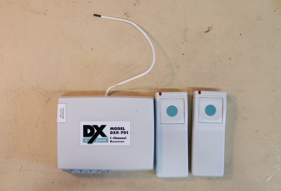
To get things started, we scribbled down the FCC ID off the back of the beige remote and dusted off a HackRF.

The digital DX code format features over a million possible codes. The DX transmitters are precoded at the factory to unique codes, so no field coding is required. The multi-button transmitters send variations of their preset codes depending on which buttons are pressed.
The remote was identified as a Linear DXT-21 talking to a DXR-701 receiver operating at 315.0MHz. Looking over the documentation, a particular statement stood out:
The system had over a million possible codes! This might have been quite the claim in 1995 when the system was first introduced, but in the era of the $100 Software Defined Radio (SDR), it gave cause for concern.
First, we tried one of the most trivial of attacks: replay. Product documentation stated that these transmitters have a range of up to 700 feet. By recording from a distance what the transmitter sends and replaying it back from a SDR, an attacker might be able to trigger the receiver if the coding format was repetitive or fixed. The results spoke for themselves:
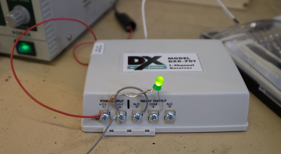
With the smell of blood in the water, we ordered a separate DXR-701 receiver and a bunch of DXT-21 remotes off of Amazon and rigged up a simple indicator light for when the internal relay strikes.
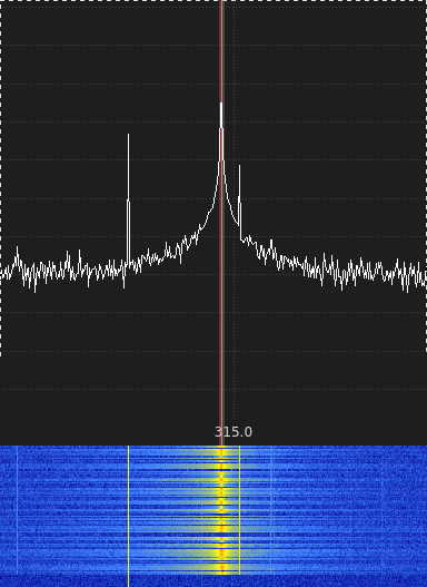
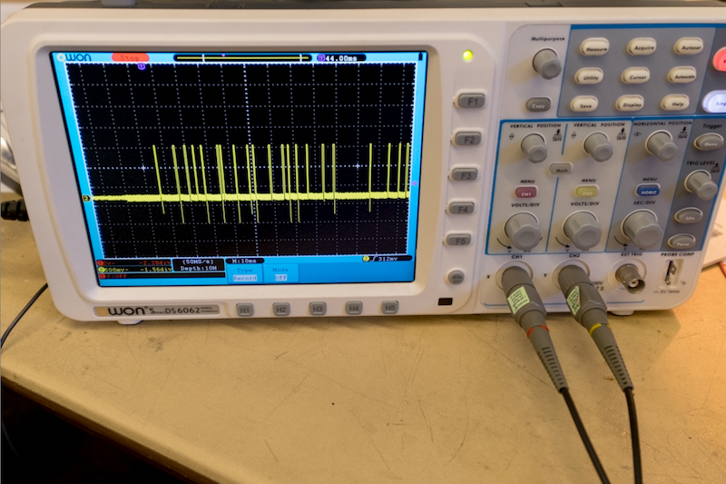
Getting the SDR out again, we began characterizing the signal. Pulling up the waterfall in GQRX and tuning to 315Mhz while tapping the transmit button, we could see very narrow bursts of data in the frequency domain. This implicated some form of amplitude modulation.
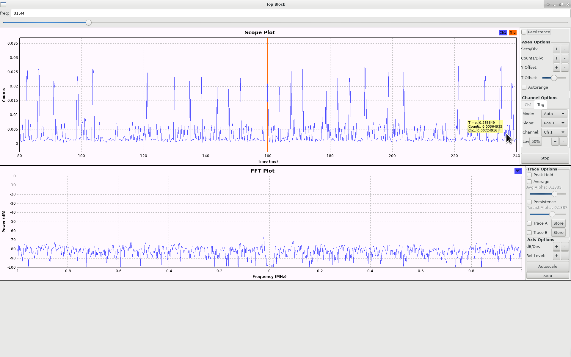
Hopping over to the time domain in GNURadio, we could clearly see data encoded some derivative of On-Off Keying: 17 relatively uniform peaks in a repeating pattern with a period of about 100ms.
DXT-21 Internals
With the general signaling understood, we decided to first peek under the covers of the remotes and see what other information we could gain.
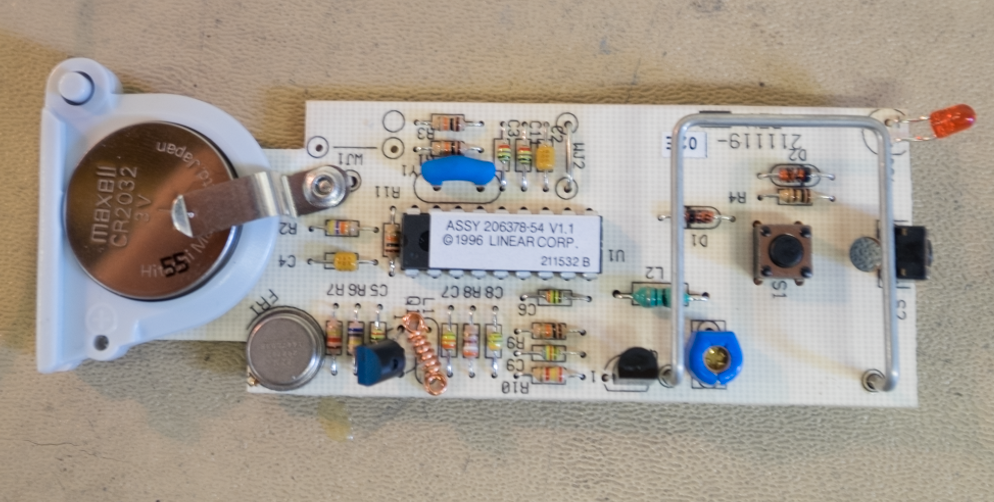
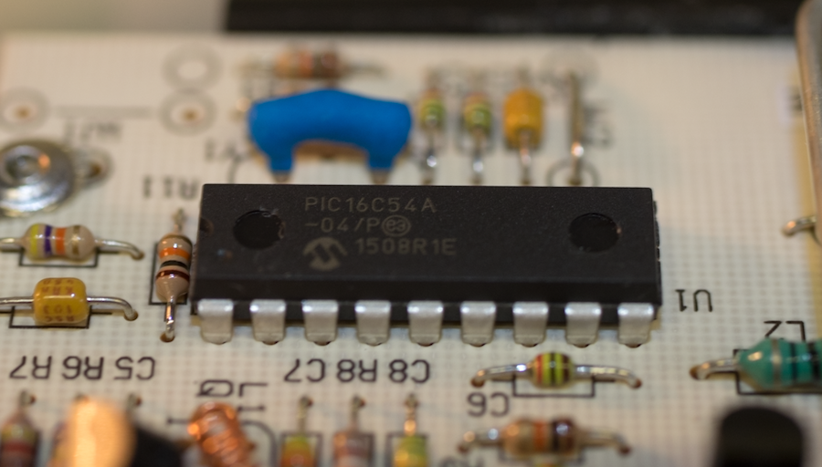
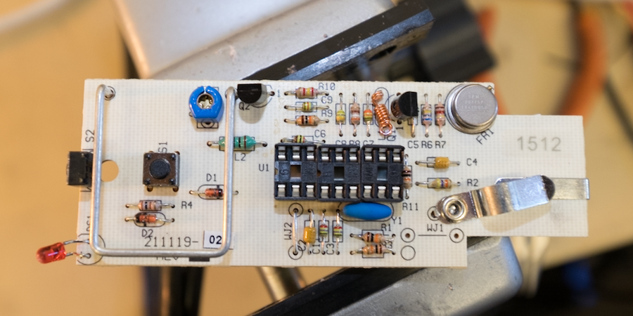
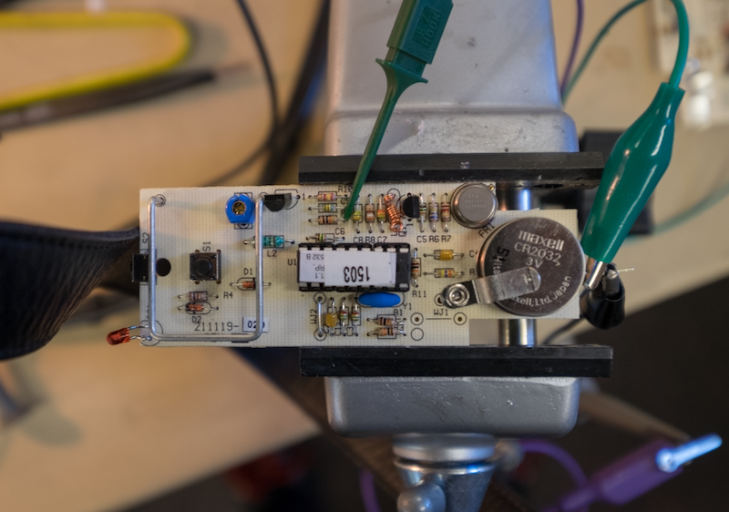
Inside we found a single-sided through-hole PCB with a very simple two-transistor transmitter with a single DIP18 microcontroller and a couple buttons. Peeling back the sticker on the controller revealed an 8-bit PIC microcontroller (PIC16C54A-04/P) with a manufacturing date code from 2015.
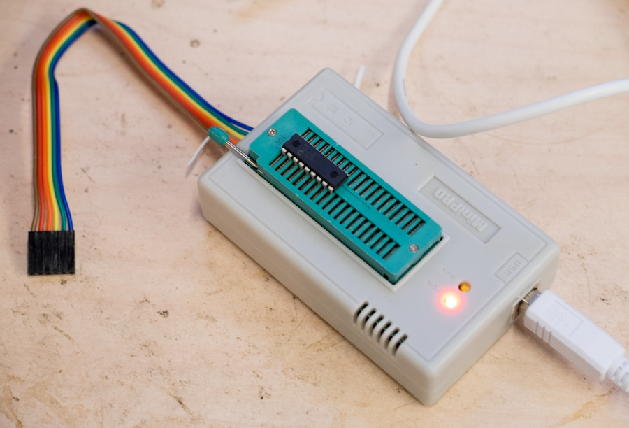
As the PIC16C series is EPROM-based, it can only be programmed once. I sucked the chips out of three of the boards and threw them into an old EPROM writer to see if I could dump the 512 byte firmware image stored onboard.
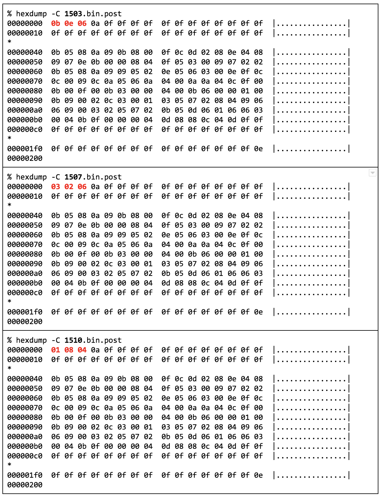
The firmware code protection bit turned out to be set. Dumping the firmware would dump XOR hashes of some preceding bytes. Comparing the dumps of these three showed that the only difference between them was within the first three bytes:
I eventually put a socket on one of the PCBs so I could easily swap between the firmwares without juggling the eventual mess of a wire harness.
DXR-701 Internals
With as much information extracted from the remotes as possible, I turned my aim to the receiver. Inside the DXR-701, I found a similar style of through-hole board construction with a few unpopulated components for the 2-channel variant. In the middle of the board sat a PIC16C56-XT/P microcontroller, identical to the one in the remote but with twice as much EPROM. Sucking out the PIC chip yielded similar scrambled results as that of the remotes.
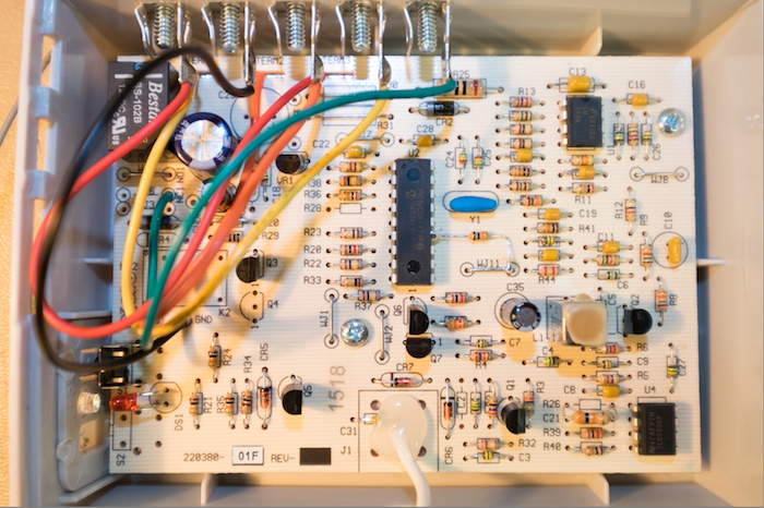
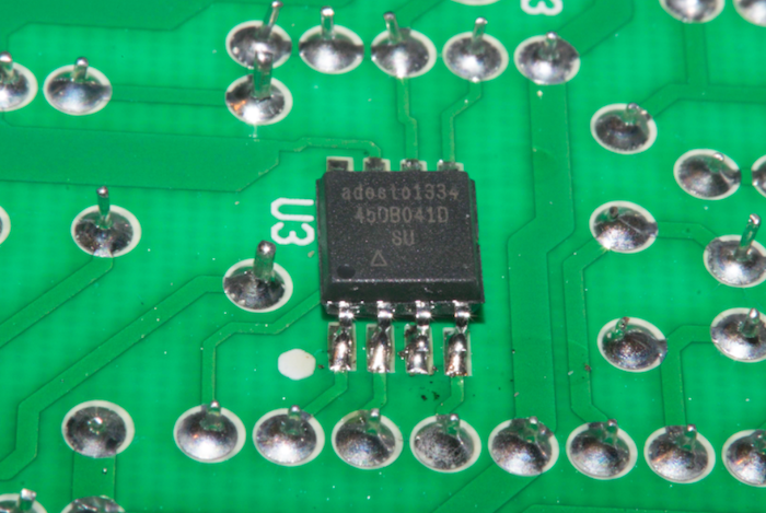
The back of the remotes had no components to speak of, but the back of the receiver held a lone Adesto 45DB041D-SU SOIC8 528K SPI flash chip positioned close to the microcontroller.
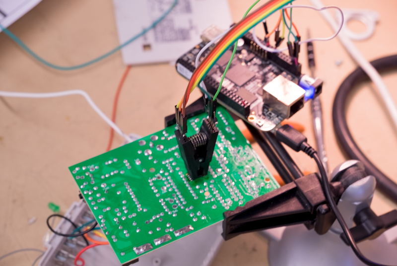
One of my favorite tools for dealing with SPI buses is the BeagleBone Black. You can quite easily get the SPI bus exposed as a device node opening a range of options from direct scripting with pyspidev to using well-developed tools like flashrom. I wired up a SOIC8 chip clip to the BeagleBone and attached it to the flash chip in circuit.
Having already paired a single remote out of the possible 32 into the receiver for testing, dumping the chip yielded some interesting results. Three distinct areas stood out. A single 0xFE at location 0x100, a single high entropy 264-byte page, and another 0xFE located at some arbitrary location.
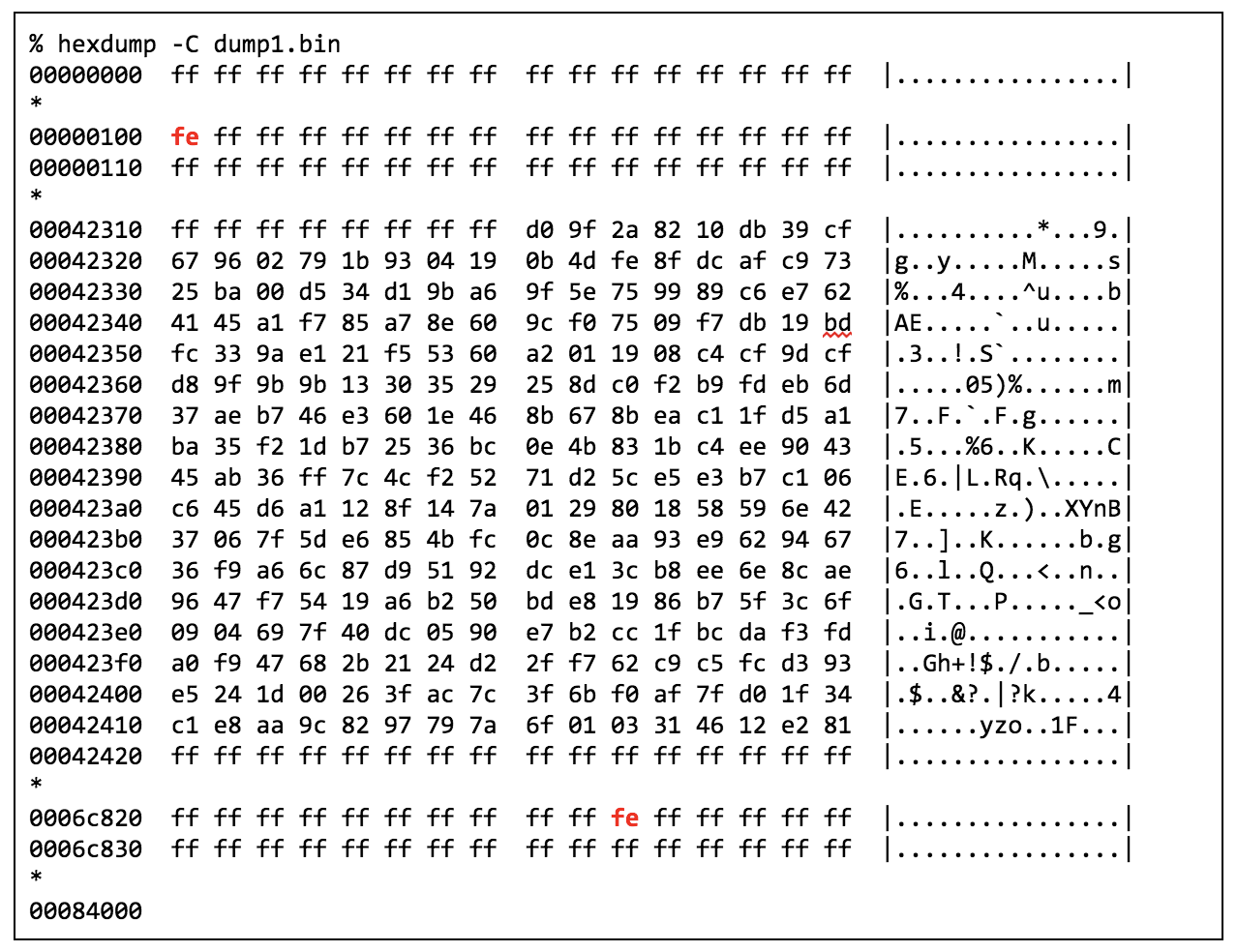
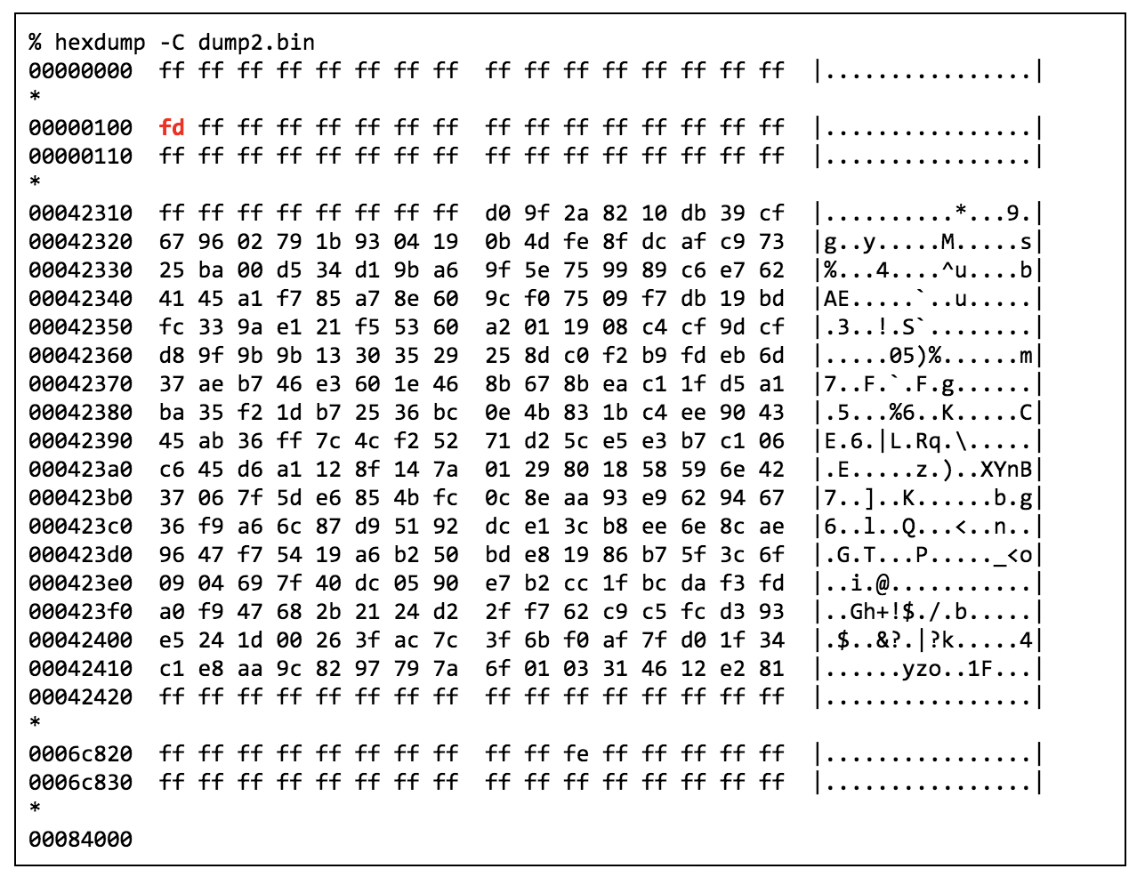
The receiver documentation made clear that the user should be careful not to program the same remote twice so I did just that and programmed a second instance. Dumping the flash after that showed the byte at 0x100 had decremented by 1, but all other data remained the same:
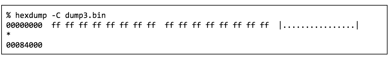
I thought this strange for so much data to be stored for a single key given that it occupies no more than three bytes in the transmitter’s firmware so I performed the forget-all-codes operation and dumped the receiver again to see what a non-programmed state looks like. Dumping that yielded a completely empty flash:
Reprogramming the same remote and dumping the flash again showed something unexpected. The high entropy page was completely gone! Only two addresses contained data.
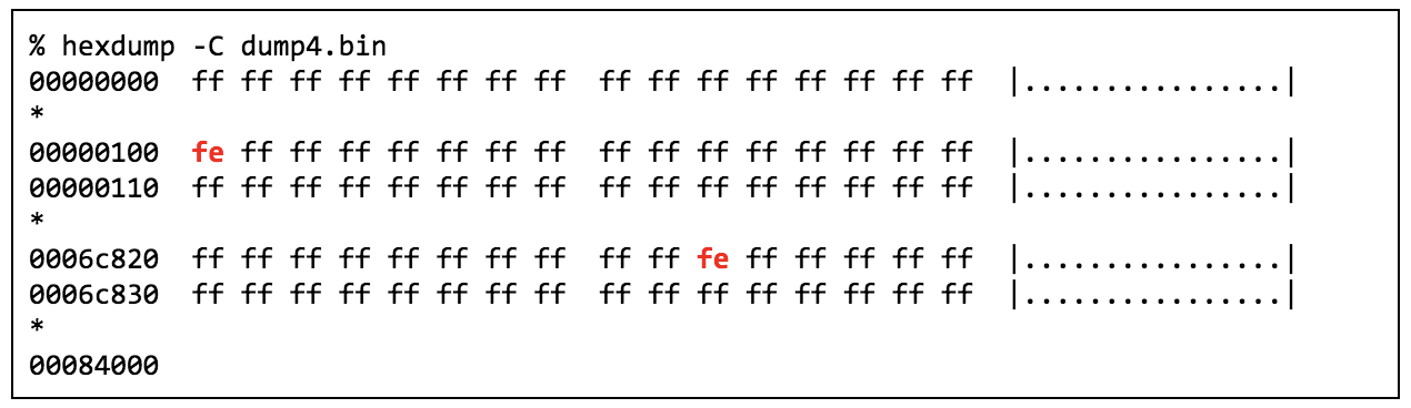
I programmed two additional remotes into the receiver and dumped the flash to confirm my suspicions.
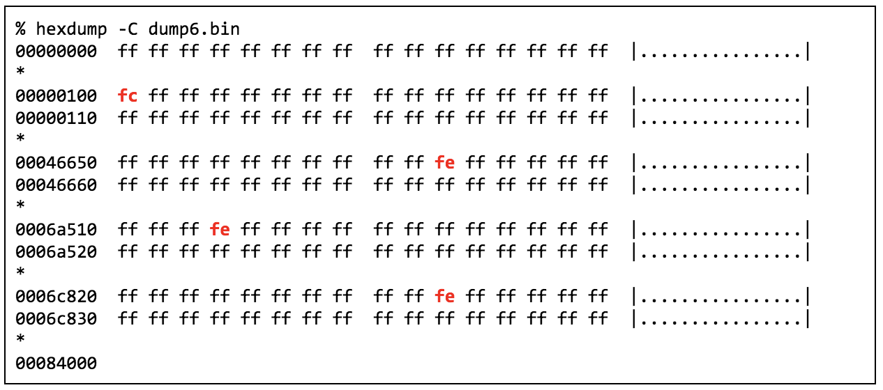
The high-entropy page was accidentally left in the flash from the factory. Probably a test pattern that wasn’t cleared. Predictably, with each additional key paired the value at 0x100 would decrement by 1 and a byte correlating to the key would be placed in the address space.
Signal Analysis
Based on these tests, it seemed odd that the receiver would have a 32-code memory limit as a key would occupy only a single byte across the expansive 528K flash. I changed the key count to 0xFE and flashed my custom image. I tried all three programmed keys and they all actuated the relay. The limit was completely arbitrary and unenforced outside of the programming mode.
This gave me a few potential avenues of attack and a series of questions. Could I identify the coding of the key to target specific flash addresses? Could that be pointed at the address of the key count? How fast could I iterate over the entire flash?
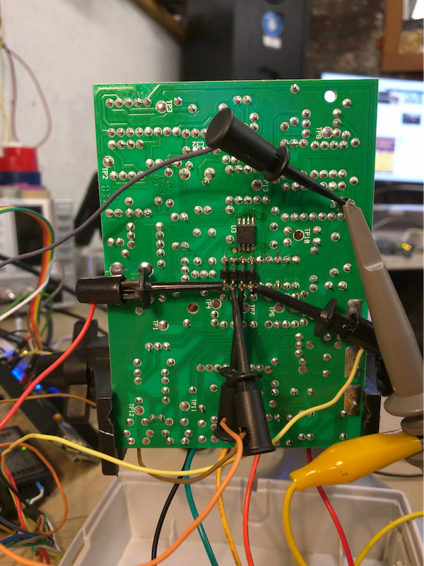
Probing around the transmitter, I discovered that two pins connecting to R9 and R7, that when driven high, would activate the the transmitter performing the OOK.
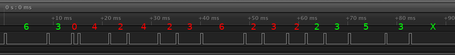
With the ability to analyze the keying digitally, I set the HackRF aside and connected my 8 channel Saleae Logic clone. I took some captures of the various remotes that I had and put them on top of each other with an SDR-sourced waveform to compare against. Much of the coding became clear:
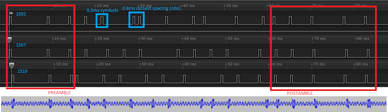
All 17 pulses were of uniform 0.5ms width spread across a fixed 85ms window. There was a common series of three pulses that appeared to be a preamble, a series of five pulses for the postamble, and a series of nine pulses that varied in spacing for different keys with no symbol being closer than 0.8ms.
Doing some napkin math, of how many ways to scratter 9 0.8ms symbols across a timespan of 47ms yielded a number close to 100 million. This immediately felt off as the sales sheet brags about having over 1 million possible codes and marketing departments are rarely apt to under-advertise a product’s capabilities.
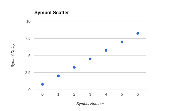
On a hunch, I logged and sorted all the inter-pulse delays that I had seen. It turned out that there were only 7 distinct values only 1.24ms apart from each other!
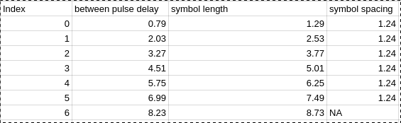
By plotting these values, it was clear that I had examples of all possible symbols:
With this knowledge in hand, I could transform the captured waveforms into numeric symbol streams consisting of a two-symbol prefix, ten-symbol key and a five-symbol postfix with an irrelevant last digit being used as retransmission deadspace and served only as an end marker for the preceding digit.
To enumerate the entire possible key space, I could have done some complicated math but computers are fast -- so I took the brute-force approach and wrote a small utility to do it for me. This generated a list of all theoretically possible keys: 16,733,080 in total. This value was still larger than the advertised one million, but it was a start.
Test Harness
To try to correlate key values to SPI flash addresses, I would need samples. Lots of samples. Much more than the three remotes I had on hand. I needed some automation. Ideally, I wanted a setup where I could stimulate the receiver with a symbol sequence of my choosing and watch what traffic, if any, occurred between the PIC16 controller and the SPI flash chip.
To make a universal transmitter which could transmit any symbol sequence, I hijacked a remote’s RF stage as I had previously burned out my HackRF’s TX frontend.
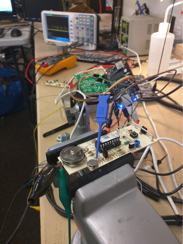
By bending the two signal pins out of their DIP socket, I could manually key the transmitter freely for up to 10 seconds before the PIC shutdown. I knew I’d want to transmit for longer periods than that, so I wired in permanent power and attached a lead to the PIC’s reset line that I could pull low between transmissions.

To drive all of this, I would need something to use as a reliable signal generator. I was already using a BeagleBone Black to do dump the SPI flash, so I decided to leverage one of the two internal Programmable Realtime Units (PRUs.) These RISC PRUs have a relatively fast 200Mhz clock and allow for single cycle IO access.
After a bit of futzing around with the instruction set, I had some PRU code and a utility that would take my symbol sequence and output the appropriate waveform all from the command line.
To correlate key values to flash addresses, I wired in my logic analyzer to the receiver and used a little-known feature of sigrok’s CLI utility to perform the live SPI protocol decoding. From that stream of SPI data, I could see what flash addresses were being accessed.
The SPI flash itself used 264-byte DataFlash pages. Data was accessed by specifying a 3-byte long locator consisting of an 11-bit page address and a 9-bit byte locator.
10-Symbol Key Fuzzing
After confirming that all the keys I had on hand were included in the output of my code generator, I grabbed a block of codes starting from a known key and passed them through the test harness.
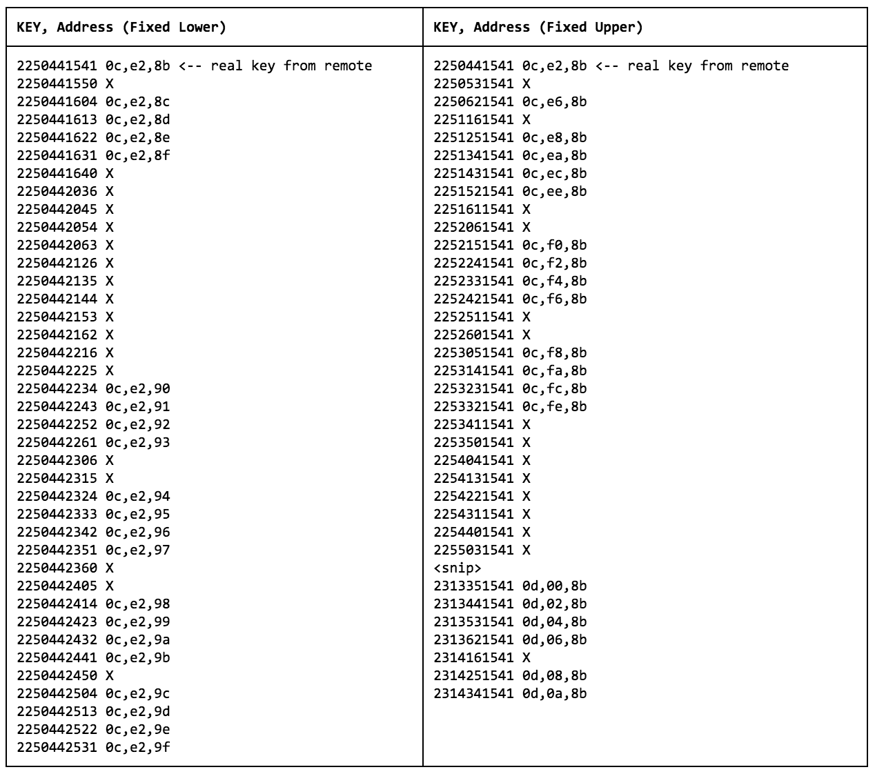
To my delight, I started seeing responses. Not only was the test harness working, but as I iterated through the code generator’s output, the byte address being accessed by the controller would increment by one. After leaving the automation running for several thousand iterations, it became clear that the last four symbols of the key got encoded into a byte offset with consistent encoding, I had a list of all 256 possible values and they were consistent across different pages. However, the flash used 264 byte pages. The 9 bytes beyond that appeared to be unaddressable.
Next, I held the last four symbols static and repeated the test, fuzzing the lower six symbols that worked as page selectors. The page selectors also began to increment by one! By mixing and matching the lists, I could address arbitrary bytes from pages 0x401 to 0x7FF.
Curiously, pages 0x00 to 0x400 were inaccessible. Even though all six of my remotes utilized same two symbol (63) prefix, there must be another page bit in what I assumed to be static two symbol prefix.
11-Symbol Key Fuzzing
By expanding the code generator to generate all possible 11 symbol codes, I could apply the same fuzzing strategy of holding the byte offset fixed and identify the lower pages as they would be encoded into the lower seven symbols. This yielded a list of 4,001 valid page addresses. Going back to our napkin math, 4,001 pages * 256 offsets = 1,024,256! Just as advertised!
However, astute readers would remember that the SPI flash is only half that size. Looking more closely at the code mappings revealed that most page addresses had two valid values.
Meaning, there are two keys that would resolve to the same address. For instance, both 33306033334 and 15306033334 map to flash address 0f,98,00 and trigger the relay. This cut the keyspace almost in half to only 2047 page selectors. This meant that there are only 524,032 truly unique remotes.
Postfix Fuzzing (Channel Selector)
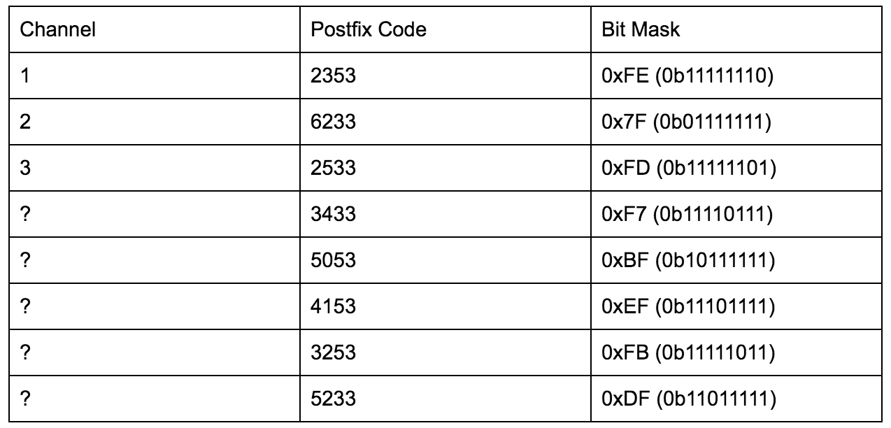
The only curious thing that remained was the long four symbol postfix and what actually got written to the flash upon pairing a remote with a receiver. After fuzzing and identifying 8 traffic generating postfixes, it turned out these four symbols selected which bit would be cleared in the flash. All six of my DXT-21 remote keys ended in ‘2353’ which resulted in the bitmask of 0xFE being applied. I had a suspicion that this is how the multi-channel remotes are implemented.
To confirm, I sourced a DXT-42 three “code” remote. Through SPI traffic monitoring, it became clear that the code is consistent regardless of which button is pressed with the only difference being which mask is applied. Channel 1 applied a mask of 0xFE just like the DXT-21s do, Channel 2 utilized a mask of 0x7F and Channel 3 utilized 0xFD.
Exploitation
Now we had the full key-encoding definition:

With this and knowlege of how to iterate over the entire key space, we can draw some conclusions about the complexity of brute-forcing these devices. Each code takes approximately 100ms to transmit and to be ingested by the receiver. Having only 524,032 unique keys, this means any given remote channel can be brute-forced in its totality in 14.5 hours, or just 7.25 hours on average, which is well within the realm of practical feasibility.
My receiver came with a dirty page with high entropy data in it out of the factory. The only “illegal” value for any given key would be 0xFF. If this manufacturing oversight is a common occurrence, then by trying 16 key combinations across the 2047 different pages, we would be able to trigger the relay in under half an hour on average. Worse yet, there is no way to tell if a unit is affected by this besides dumping the flash chip manually. Force clearing the memory of the receivers and re-pairing the remotes is a must.
When combined with the inherent vulnerability to replay attacks, the Linear DX system might be good enough to turn some Christmas lights off and on, but I wouldn’t trust it for its intended use of physical access control.
Code used for this project may be found on my github, here.